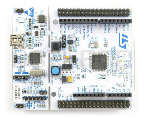

The Nucleo board is connected via USB to a host (Mac, Windows, or Linux), the debugging and serial wires are connected to the target.
NUCLEO F401RE USB DEVICE HOW TO
This document describes how to use a Nucleo STM32L476RG board to connect to a target STM MCU for firmware downloading, debugging and serial terminal connection. RadioShuttle Sketch Installation for LongRa.RadioShuttle Sketch Installation for Eagle.RadioShuttle Program Installation for Turtle.RadioShuttle Sketch Installation for ECO Power.
NUCLEO F401RE USB DEVICE FULL
Perhaps they've used a voltage regulator that can't regulate the full 500mA, or maybe they're reserving the extra current overhead for the non-user-accessible features of the Nucleo. Note also that the doc says that 300mA is all that is possible. It is now your responsibility to always plug into a 500-mA capable port :) If you short over SB1 then the main microcontroller will always be powered. It's the MOSFET in the lower-left of the first page. There is a solution, however! Find T2 on the schematic. Unfortunately this jumper also limits the current draw to 100mA! You can't have high-current and non-enumeration at the same time. There is a jumper (JP1) that you can use to enable the main microcontroller without enumeration.

This is described in the user manual, section 5.3.1. It simply won't power up the main microcontroller until an enumeration takes place. However, the Nucleo board doesn't implement the second option. Second: How the Nucleo implements these rules: There are a few schemes where the device can determine that high-current is available. If the device is plugged into a non-intelligent port (wall wart, battery pack, etc) then enumeration can't take place. The host may then grant permission for the device to draw more. During the enumeration the device can let the host know that it wants more than 100mA. If the device is plugged into a computer, USB hub, etc, then there is an intelligent conversation that takes place between the device and host. Here is a nice document by Maxim that describes the details. There are various methods for the device to know how much current it is allowed to draw. It is the responsibility of the device, not the host, to limit current consumption. The host device dictates to the device how much current it can draw. Generally this higher current is 500mA (max) although there are further exceptions that allow more current. After connection, if the device determines that it is allowed to take more current, it can do so.

The USB specification dictates that a device (the Nucleo in this case) will only draw 100mA max when first connected to a host (the computer or power source). As you can see by the name, they intend that you just drop some solder between the two contacts. The quick answer is that you need to create a short across SB1 ("solder-blob 1"). When soldered, it physically bypasses the USB Power Management mosfet, connecting USB 5V directly to the target board and 3.3V regulator. Solder the SB1 (USB Power Management Bypass). (Additionally, remove the JP5 jumper just to make sure) Otherwise it's a waste of power, as small as it may be. If you don't need the Programmer and Debugging while on a usb battery pack, use the 5V pin. Simply putting this jumper on should do the trick.Ĭut a usb cable, and wire the V+ to the either the E5V pin (Make sure JP5 is set on pins 2-3, for external power.), or the 5V pin, depending on if you want the ST/Link side of the board to be on as well or not. When ON, it signals the ST/Link that External Power is being used, and should enable the power mosfet anyway. If it successfully enumerates with the requested power, it enables the USB power Mosfet. When OFF, the ST/Link part of the board attempts to enumerate with high power request. JP1 is the usb power limit bypass jumper. Here is the schematic of the Nucleo board including its power circuitry: Question: Is there some physical re-configuration I have to do to allow the Nucleo to be USB-powered by a 5V-Usb-out battery pack, and to successfully draw power (about 250 mA in my case) from the board's 3.3V out pin? The Nucleo board's LD1 (LED) just continuously blinks at 1 Hz The transmitter module isn't transmitting (I'm not receiving packets on remote unit) I get 1.1 V for the multimeter reading on the 3.3V out pin of the Nucleo board the transmitter module successfully transmits (I successfully receive packets on remote unit)Ĭase B (unsusccessful): But when I connect/power the Nucleo board with a USB cable to a Battery pack (one of those phone backup-battery packs with 5V output 1A), then:.The sensor draws power (~200 mA) from the Nucleo board's 3.3V out pin.Ĭase A (successful): When I connect/power the Nucleo board with a standard USB (5V) cable connection to my PC, then: I have a wireless-transmitter module connected to a Nucleo board.


 0 kommentar(er)
